
Overview
Users of electromagnetic transients (EMT) simulation programs (such as PSCAD/EMtdC) often face difficulties in obtaining data and developing cases suitable for their studies. Many utilities have the data available for their entire system in loadflow programs, but a great deal of effort is required to re-enter the network data for use in EMT programs.
We developed the E-TRAN translator to automate the processes that were repeated for each new study performed for their customers. E-TRAN not only saves considerable time and effort, but it bestows confidence in the study results.

Direct translation of Power System Data into PSCAD
Auto-Routing & Graphical Representation
Formation of Network Equivalents
Initialization of Machines, Generators & Sources
E-TRAN Runtime Library for PSCAD
Sanity Check & Data Verification
Compatible with PSCAD V4.6 and V5
Matching the Loadflow in PSCAD
Network Equivalents

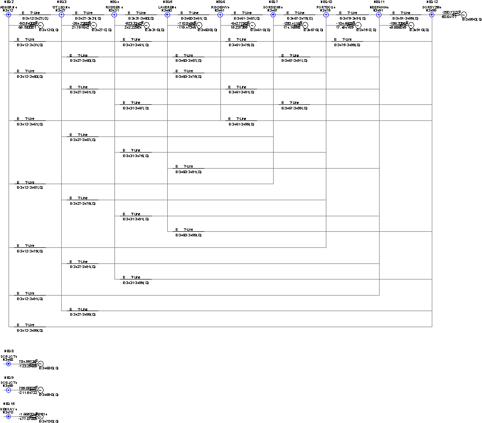
Example 1
The first image shows a portion of a network near a bipolar HVDC converter station The circuit is loaded in PSCAD V4 and was directly generated by E-TRAN from a PSS/E .raw input file. (Click on the image to download a higher resolution picture.)
The original circuit was more than 18,000 busses, but, for this example, E-TRAN directly translated only 1 bus away (which resulted in a 15 bus circuit) from the HVDC bus and formed a network equivalent of the remaining circuit.
The second image shows the equivalent network on a sub-page. The voltage magnitude and phase angle of the equivalent sources are automatically calculated to match the power flow of the solved loadflow. Note the multi-port equivalent is valid for steady state as well as for open/short circuit conditions.
E-TRAN converted the circuit, using only the PSS/E .raw file, directly into a PSCAD Version 4 .psc file in three phase Single Line Diagram (SLD) format.
Example 2
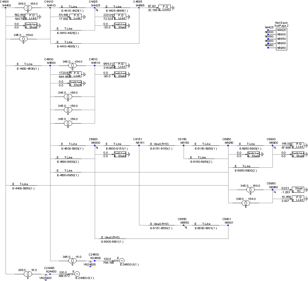
The first image shows a portion of a small network at a 345 kV bus. The circuit is loaded in PSCAD V4 and was directly generated by E-TRAN from a PSS/E .raw input file.
E-TRAN directly translated only 2 busses away from the main bus (which resulted in a 15 bus circuit) and formed a network equivalent of the remaining circuit.
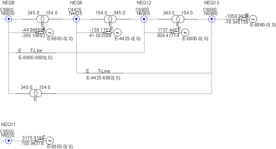
The second image shows the equivalent network on a sub-page. Note that the interface busses are at different voltage levels and a transformer is automatically used for the off-diagonal branches instead of a pi section transmission line.
E-TRAN creates a log file which contains details of the conversion process and numerical output of the system admittance matrices. The log file for this small system is in the file “Example2.txt”.
In this case the entire circuit was only 160 busses, so it could have easily been translated and run in PSCAD without the need for any network equivalent.
Frequently Asked Questions
We update our tools regularly to have the latest PSSE formats supported by E-TRAN. Currently versions 26 ,29, 30, 31, 32, 33, 34 and 35 are supported with the latest E-TRAN version. Some older version may be supported in previous versions of E-TRAN.
E-TRAN can generate three-phase Single Line Diagram (SLD) circuit .psc or .pscx files for PSCAD V4.2, and x4.6.
E-TRAN can generate three-phase Single Line Diagram circuit in .pscx files for PSCAD V4.5+ and V5.
Versions 4.2 and before are no longer supported by the latest E-TRAN software.
You can send e-mail to the Electranix Corporation at e-tran@electranix.com for all software related updates and support.
You can visit http://www.PSCAD.com or you can send e-mail to the PSCAD Support team at
support@PSCAD.com . PSCAD is developed and supported by the Manitoba HVDC Research Centre Inc
(http://www.hvdc.ca).
The E-TRAN program is always under development. Future releases will translate transient stability
data in addition to the loadflow data and will form dynamic equivalents. These will include the effects of machine inertia and controls in the network equivalents. We also plan to support additional input formats (in addition to the PSS/E .raw format). If you have any ideas or suggestions for improvements to E-TRAN, please send them to us at e-tran@electranix.com.
There are a number of reasons this can occur but the most common issue is an unsolved .raw is being
used as an input file. Check that the .raw file being used is “solved” in PSS/E. Check that the file used in
E-TRAN has the updated loadflow solution saved in it. Also check that fundamental frequency behaviour
of any models in the E-TRAN Substitution Library match that of the standard E-TRAN components (If you
turn off the Substitution Library, does the solution then match?). Finally, check DC links to see if they are operating correctly. The DC link controls may have to be adjusted to work in very weak systems (If you use the “Infinite Bus” option in the DC link component, does the loadflow then match? For further support contact e-tran@electranix.com.
The PSCAD Master library models performs RMS or instantaneous PQ measurement (for example, the
sum of VA.IA + VB.IB + VC.IC etc.), which includes the effect of all sequence components and the effect
of harmonics. The E-TRAN PQ measurements devices (or voltage measurements) measure the +ve
sequence, fundamental frequency quantities (used in loadflow programs), not the instantaneous or RMS quantities. This effect is particularly obvious at locations where there are significant harmonics (such as near a commutating model of a DC link). If the instantaneous quantities being measured are sinusoidal, distortion free and balanced (i.e., only +ve sequence), the results should match.
Get Software Today
Free Trial
e-tran@electeanix.com.